TANN THONA

Department of Telecommunication and Electronic Engineering

Hot

Post Top Ad

Wednesday, December 5, 2018

Analog Read to Control LED Light

11:33 PM 0

Analog Read Control LED Light

1. Objective

The objective of this project is talk about, how to use analog read to control LED light colors. We use voltage divider input to analog pin and read value to control LED with digital pin.

2. Electronic Requirement

  • Arduino Uno
  • USB Cable
  • Breadboard
  • LED (or RGB)
  • POT-HG (Variable Resistor)
  • Resistor 330Ohm or 220Ohm (Digital pin --> Resistor --> LED)
  • Electronic Wire

 3. Build Circuit

The first build circuit like Fig1.1.
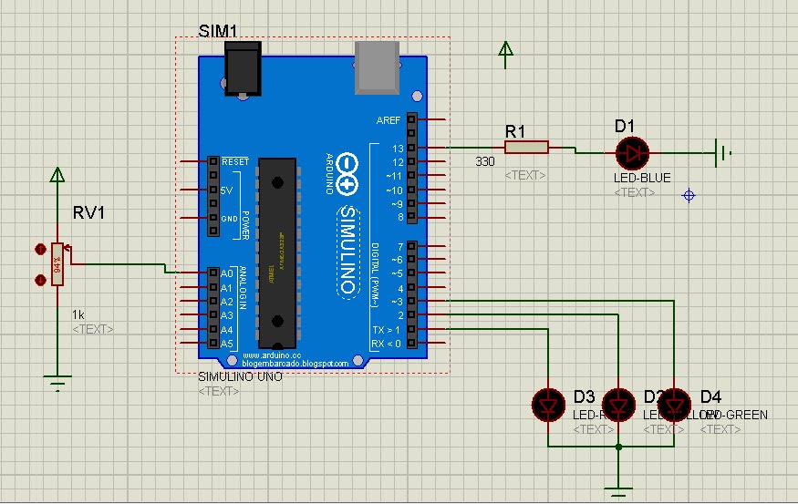

Fig1.1 Analog read to control LED lights.

 Arduino Code:
// Coding by Tann Thona (26/03/2017), Adviser: Chann Tola  
float x=0;
float y=0;
int t =300;
void setup()
{
pinMode(13,OUTPUT);
pinMode(1,OUTPUT);
pinMode(2,OUTPUT);
pinMode(3,OUTPUT);
//pinMode(10,OUTPUT);
}
void loop()
{
y = analogRead(A0);
x=(5*y)/1023;
if(x>3)
{
digitalWrite(13,HIGH);
}
else
{
digitalWrite(13,LOW);
}

// LED Three color (RGB)

digitalWrite(1,HIGH);
digitalWrite(2,LOW);
digitalWrite(3,LOW);
delay(t);
//-------------------------
digitalWrite(1,LOW);
digitalWrite(2,HIGH);
digitalWrite(3,LOW);
delay(t);
//-------------------------
digitalWrite(1,LOW);
digitalWrite(2,LOW);
digitalWrite(3,HIGH);
delay(t);
//-------------------------
}


4. Result

When we run this code in Arduino software and output to circuit, LED has light or dark is depend on value of POT-HG that we change. While we change POT-HG value power supply in put voltage to Pin Analog (A0) of Arduino and Pin Digital (13) red from A0 and output to LED. Whereas RGB is change color one by one of the three color with delay time in code.


Royal University of Phnom Penh
Faculty of Engineering
Dep. Telecommunication and Electronic Engineering

Group Member:
1. Tann Thona

2. Thach Soveasna
3. Chhoy Noreath
4. Neth Channa
5. Mok Vira

Instructor: Prof. Chann Tola
Date: 26 March 2017
Read More

LCD 16x2 Automatic Scroll Letter Left to Right

5:06 PM 0

LCD 16x2 Display Automatic Scroll Letter

1. Objective

The objective of project is talk about, how to use LCD Screen 16x2 and display text on screen. On the first row of screen show text “RUPP ^_^ “and second row show “ TELECOM 2017” . In second row of screen display text that move text from left to right one by one. If which letters move to line fines limit screen that letter show back on the first column of left screen.

2. Electronic Requirement

  • Arduino Uno
  • USB Cable
  • Breadboard
  • LMO16L (LCD 16x2)
  • Potentiometer (POT-HG Variable Resistor)
  • Resistor (220Ohm)
  • Electronic Write

3. How to Build it?

The first build circuit like below on Fig1.1.

Fig1.1. LCD 16x2 display connection diagram

Arduino Code:

// Write code by Tann Thona (15/03/2017), Adviser: Chann Tola    


// include the library code:
#include <LiquidCrystal.h>

// initialize the library with the numbers of the interface pins
LiquidCrystal lcd(12, 11, 5, 4, 3, 2);

char Telecom[16] = {' ',' ','T','E','L','E','C','O','M',' ',' ','2','0','1','7',' '};

void setup()
{
// set up the LCD's number of columns and rows:
lcd.begin(16, 2);
lcd.setCursor(4, 0);
lcd.print("RUPP ^_^");

}// void setup

void loop()
{
lcd.setCursor(0, 1);
for(int j=0;j<=15;j++)
{
lcd.print(Telecom[j]);
}
lcd.setCursor(0, 1);
delay(100);
int swap = Telecom[15];
for(int i=15;i>0;i--)
{
Telecom[i] = Telecom[i-1];
}
Telecom[0] = swap;

}


4. Result

When we run this code in Arduino software and output to circuit, the text is automatic display on the LCD screen. The text “RUPP ^_^” is static show on the first row of LCD screen. Second row of LCE screen we see the text “TELECOM 2017” is automatic move step by step depend on delay in code on Arduino software like Fig1.2.


Fig1.2. Result LCD 16x2 display automatic scroll letter left to right


Royal University of Phnom Penh
Faculty of Engineering
Dep. Telecommunication and Electronic Engineering

Group Member:
1. Tann Thona

2. Thach Soveasna
3. Chhoy Noreath
4. Neth Channa
5. Mok Vira

Instructor: Prof. Chann Tola
Date: 15 March 2017


Read More

Tuesday, December 4, 2018

7 Segment 4 Digits Display Count Up Number

7:12 PM 0

7 Segment 4 Digits Display

1. Objective

The objective of this project is talk about, how to use 7 segment 4 digits and display count up from 0 to 9999.

2. Electronic Requirement

  • Arduino UNO
  • USP Cable
  • 7 Segment 4 digits (Cathode Type) 
  • Breadboard
  • Electronic Wire
  • Resistor x4 (330Ohm or 220Ohm)
    • Arduino pin 5 --> R1 --> 7 Segment D1
    • Arduino pin 4 --> R2 --> 7 Segment D2
    • Arduino pin 3 --> R3 --> 7 Segment D3
    • Arduino pin 2 --> R4 --> 7 Segment D4

    3. How to Build it?

     The first build circuit like below on Fig 1.1 automatic count up number.

    Fig 1. 7 segment 4 digits display automatic count up number 0 to 9999
    // Write code by Tann Thona (25/02/2017), Adviser: Chann Tola
    int PIN_A = 12;
    int PIN_B = 11;
    int PIN_C = 10;
    int PIN_D = 9;
    int PIN_E = 8;
    int PIN_F = 7;
    int PIN_G = 6;
    int DL4 = 5;
    int DL3 = 4;
    int DL2 = 3;
    int DL1 = 2;
    int i = 0;
    int j = 0;
    int n = 0;
    int k = 0;
    int h = 0;
    int Arduino_Pins[7] = {PIN_A, PIN_B, PIN_C, PIN_D, PIN_E, PIN_F, PIN_G}; // an array of pin numbers to which LEDs
    int Segment_Pins[10][7] = {{1,1,1,1,1,1,0}, // 0
    {0,1,1,0,0,0,0}, // 1
    {1,1,0,1,1,0,1}, // 2
    {1,1,1,1,0,0,1}, // 3
    {0,1,1,0,0,1,1}, // 4
    {1,0,1,1,0,1,1}, // 5
    {1,0,1,1,1,1,1}, // 6
    {1,1,1,0,0,0,0}, // 7
    {1,1,1,1,1,1,1}, // 8
    {1,1,1,1,0,1,1}, // 9
    };
    int DELAY = 1;
    int TIME = 0;
    void digit4()
    {
    digitalWrite(DL1,0);
    digitalWrite(DL2,1);
    digitalWrite(DL3,1);
    digitalWrite(DL4,1);
    for(j=0;j<7;j++) {
    digitalWrite(Arduino_Pins[j],Segment_Pins[i][j]);
    }
    delay(DELAY);
    }
    //=============================
    void digit3()
    {
    digitalWrite(DL1,1); // change 1 to 0 and 0 to 1 (for 7segment anoth type)
    digitalWrite(DL2,0);
    digitalWrite(DL3,1);
    digitalWrite(DL4,1);
    for(j=0;j<7;j++)
    {
    digitalWrite(Arduino_Pins[j],Segment_Pins[n][j]);
    } // end loop j
    delay(DELAY);
    }
    //==============================
    void digit2()
    {
    digitalWrite(DL1,1);
    digitalWrite(DL2,1);
    digitalWrite(DL3,0);
    digitalWrite(DL4,1);
    for(j=0;j<7;j++)
    {
    digitalWrite(Arduino_Pins[j],Segment_Pins[k][j]);
    } // end loop k
    delay(DELAY);
    }
    //==============================
    void digit1()
    {
    digitalWrite(DL1,1);
    digitalWrite(DL2,1);
    digitalWrite(DL3,1);
    digitalWrite(DL4,0);
    for(j=0;j<7;j++)
    {
    digitalWrite(Arduino_Pins[j],Segment_Pins[h][j]);
    } // end loop j
    delay(DELAY);
    }
    void setup()
    {
    // put your setup code here, to run once:
    pinMode(PIN_A, OUTPUT);
    pinMode(PIN_B, OUTPUT);
    pinMode(PIN_C, OUTPUT);
    pinMode(PIN_D, OUTPUT);
    pinMode(PIN_E, OUTPUT);
    pinMode(PIN_F, OUTPUT);
    pinMode(PIN_G, OUTPUT);
    pinMode(DL1, OUTPUT);
    pinMode(DL2, OUTPUT);
    pinMode(DL3, OUTPUT);
    pinMode(DL4, OUTPUT);

    }
    void loop()
    {

    for(i=0;i<10;i++)
    {
    for(TIME=0;TIME<=250;TIME++)// Simulation (TIME=0;TIME<=250;TIME++)
    {
    digit4();
    digit3();
    digit2();
    digit1();
    //delay(1);
    }
    // Condition Count Up

    if(i==9)
    {
    n++;
    //----------------
    if(n>9)
    {
    k++;
    //----------------
    if(k>9)
    {
    h++;
    //----------------
    if(h>9)
    {
    h = 0;
    } // end if(h>9)
    } // end if(k==9)
    //----------------
    if(k>9)
    {
    k = 0;
    }
    } // end if(n==9)
    //----------------
    if(n>9)
    {
    n = 0;
    } // end if (n>9)
    } // end if (i==9)

    } // end time

    } // End Void Loop


    4. Result

    Now we get a result that 7 segment 4 digits  display are started from 0 to 9999 with count up one by one per second in automatically like video below.


    Royal University of Phnom Penh
    Faculty of Engineering
    Dep. Telecommunication and Electronic Engineering

    Group Member:
    1. Tann Thona

    2. Thach Soveasna
    3. Chhoy Noreath
    4. Neth Channa
    5. Mok Vira 


    Instructor: Prof. Chann Tola
    Date: 25 February 2017
    Read More

    Monday, August 6, 2018

    Arduino Project Set Real Time Control Light 7 Segment

    11:54 PM 1

    Set Real Time Control Light Using 7 Segment


    1. Abstract

    Traditionally electrical light control by Time that regulate the electricity to these device. Time control light works by making everything in your house that turn on or turn of automatic controlled using technology control and do job that we would normally do manually. Light automatic take care of a lot of different activities in the house.

    2. Introduction

    In this project we want to do how to turn ON/OFF LED by press button as a switch to control Light of LED. We have three button for set time to turn on and turn of LED light. we used Real Time Clock (DS3231 module) to keep tract of the time even if the microcontroller is disconnect the main power because RTC run on its own batter like our clock. Using two of 7 segments cathode to display time by get real time from DS3231 module.
     

    3. Objective

    The main objective of this project is: that we are control light at our home using simple circuit.
    • Display Real Time on 7 segment
    • Set Time Automatic Turn ON LED Light
    • Set Time Automatic Turn OFF LED Light

    4. Electronic Requirement

    Electronic requirement use in this project:
    • Arduino Meg 2560
    • RTC DS3231 Module
    • 7 Segment Two Digit Cathode Type (x2)
    • Button (x3)
    • Resistance 330 Ohm (x6)
    • LED Red(x2) Wite(x1)
    • Breadboard (x1)
    • USB Connected from Arduino to Computer
    • Jumper Wire

    5. Methodology

    To create this project we use Arduino Meg 2560 as a main controller and 7segment show time clock, button set time such as minute and hour and LED turn on/off light. RTC DS3231 module to keep the time alive, and Arduino as a software for transfer the data from device to laptop or computer.
    • Controller
    The Arduino Mega is a microcontroller board based on the ATmega2560. It has 54 digital input/output pins, 16 analog inputs, 4 UARTs (hardware serial ports), a 16MHz crystal oscillator, a USB connection, a power jack and a reset button.

    Figure 1: Arduino MEGA 2560)

    • RTC DS3231 Module
    We need to use Real-time Clock (RTC DS3231) to keep tract of the time even if we program the microcontroller or disconnect the main power because RTC run on it own batter like our clock.
    The DS3231 is low-cost, highly accurate real-time which can maintain hours, minute, and seconds. This module work on both 3.3v and 5v that make it suitable for using with microcontroller (Arduino).

    Figure 2: DS3231 Real-time Clock Module

    • 7 Segment Cathode Two Digit
    7 Segment (cathode type) has 10 pins. 2 pins are GND (one for one’s digit) and others 8 pins are get power source for display number.


    Figure 3: 7Segment Cathode Two Digit

    • Button
    Button is similar switch too. If we press button it like switch open, but if we release it like switch close. We use button in this project to set time for torn on the light and turn off the light.

    Figure 4: Button

    • LED
    We use LED to show light depend on time that we set turn on or turn off.


    Figure 5: LED

    5.2 Circuit Diagram

    Connect Arduino pins to RTC and 7 Segment like diagram bellowed:
    • RTC DS3231 Module
    Table Connection RTC to Arduno

    Figure 6: The circuit of connection from Arduino MEGA to RTC

    • 7 Segment Cathode Two Digit
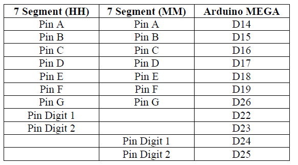
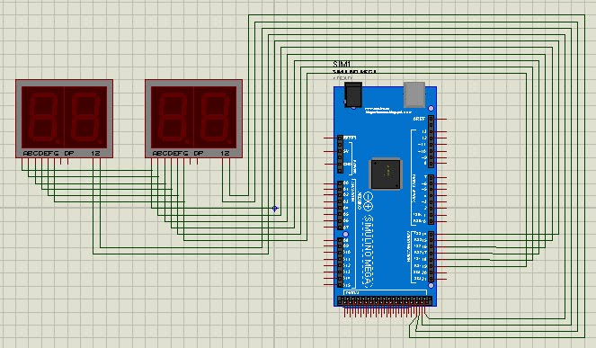
    Table Connection 7 Segment to Arduino


    Figure 7: The circuit of connection from Arduino MEGA to 7 Segment

    5.3 Algorithim of Project

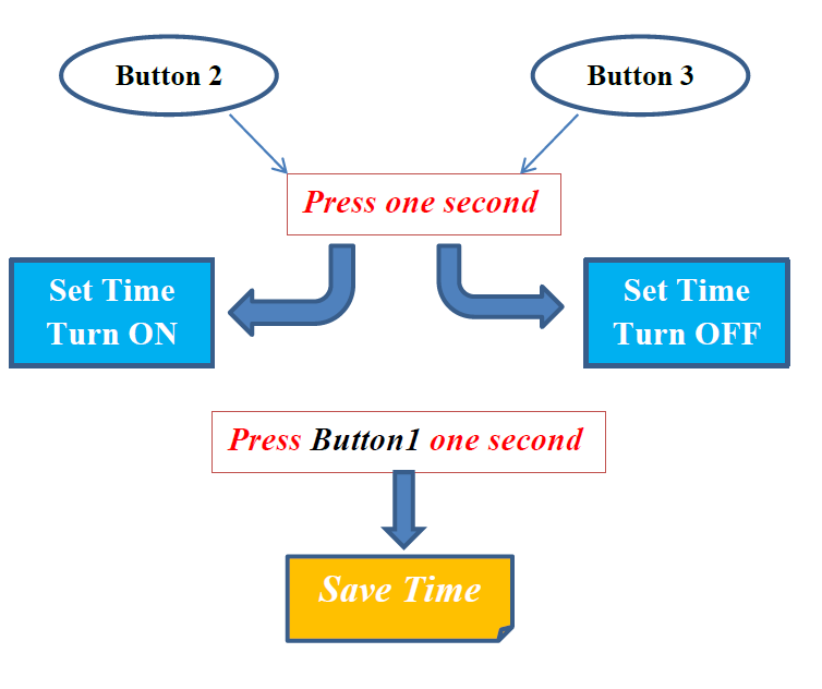
    For this project we have 3 buttons to set time turn on and turn off LED light. The first button is use for save time and change digit edit time value. Second button use for go to set time turn on LED light and decrease time value. The last button use for go to set time turn off LED light and increase time value. DS312 module is keeping track of the time and 7 Segment display clock number.

    Figure 8: Full Diagram of Project

    Flow Chart Process

    5.4 Coding

    First open arduino software plus Arduino Mega USB Cable to computer and the select port:


    After connect pin RTC DS3231 module like above then upload code set real time to RTC like below:

    //#include <SPI.h>
    #include <DS3231.h> //Library for RTC module (Download from Link in article)
    DS3231 rtc(SDA, SCL);
    void setup()
    {
    Serial.begin(9600);
    //SPI.begin(); /* Enable the SPI interface */
    rtc.begin(); // Initialize the rtc object
    rtc.setTime(13, 52, 00); // Set the time to 12:00:00 (24hr format)
    rtc.setDate(13, 3, 2018); // Set the time to 12:00:00 (24hr format)
    }
    Void loop()
    {
    }

    *Note: You have to add library DS3231 in to this software.

    Then download code and upload to your arduino: Download Code


    6. Result

    After upload code to Arduino already we get result like below:

    • 7 Segment display real time clock by get time from DS3231.
    • Button 2 (Middle): press a second 7 Segment will go to set time turn on LED mode. In mode set time if click less than a second on Button it will increase number on 7 Segment.
    • Button 3 (Right): press a second 7 Segment will go to set time turn off LED mode. In mode set time if click less than a second on Button it will decrease number on 7 Segment.
    • Button 1 (Left): press a second in set time mode it will save time value. But if we click less than a second it will change digit for edit number of time.
    • LED will turn on/off when time we set the same real time.


    Royal University of Phnom Penh
    Faculty of Engineering
    Dep. Telecommunication and Electronic Engineering

    Group Member:
    1. Tann Thona
    2. Sim Pichdany
    3. Ven Seyha
    Instructor: Prof. Kuong Samnang
    Date: 16 March 2018
    Read More

    Thursday, August 2, 2018

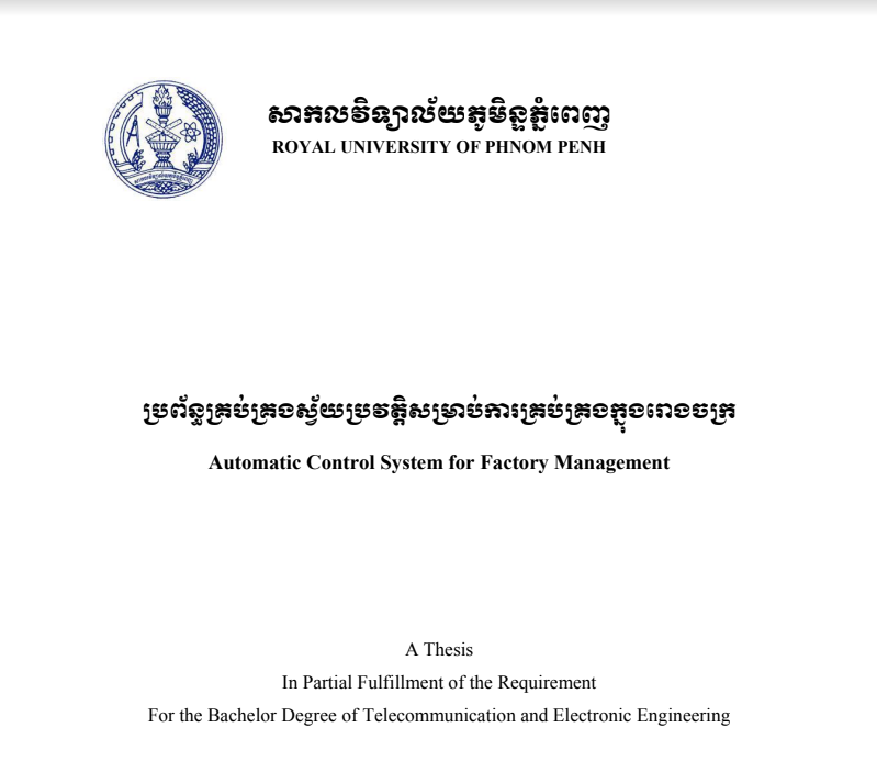
    Presentation Slide Automatic Control System for Factory Management

    12:14 AM 0

    Automatic Control System for Factory Management


        Download:  PDF   PowerPoint


    Read More

    Post Top Ad